







How to Test Power Bank Fast Charging: USB-C PD, PPS, Output Power and Compatibility Checks for OEM Buyers
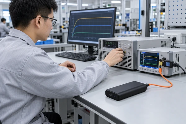
A fast-charging claim should be tested at the USB port of the finished power bank, not inferred from the charging IC or copied from a catalogue. For each claimed mode, confirm what the port advertises, negotiate that mode with suitable test equipment, apply the specified load and record voltage, current, power, temperature and shutdown behaviour.
The test also needs to cover more than a fully charged sample on an open bench. Output can change as battery state of charge falls, when a second port is used, when the enclosure becomes warm or when a different cable is connected. A “45W PD” label is useful only when the buyer knows which port delivers 45W, at which voltage and current, for how long, and under which conditions.
This guide is written for importers, private-label brands and product managers preparing an OEM power bank specification or sample-approval plan. It is not a laboratory safety procedure. High-power lithium battery testing should be carried out by trained personnel with suitable loads, protected fixtures, temperature monitoring and defined stop rules.
What should a power bank fast-charging test prove?
The short answer is that the finished SKU can negotiate and sustain every charging mode stated in the approved specification.
A useful test record answers these questions:
| Question | Evidence to keep |
|---|---|
| Which charging protocol is supported? | Protocol-analyser capture showing the advertised source capabilities and the accepted request |
| Which port provides the claimed wattage? | Port map, negotiated voltage and current, and measured output power |
| Can the product sustain that output? | Time-based voltage, current and temperature log under the agreed load |
| Does performance change as the battery empties? | Results at defined battery state-of-charge checkpoints |
| What happens when two ports are used? | Tested port combinations, total power and per-port allocation |
| Does the power bank recharge at the claimed speed? | Input negotiation, input power, recharge time and temperature record |
| Does it work with the intended devices? | Compatibility matrix using named phones, tablets, laptops and cables |
| How does it respond to a fault or disconnect? | Protection trip, recovery and reconnection results |
Do not replace this evidence with a photograph of a USB power meter showing one peak value. A brief 44.8W reading may be genuine, but it does not show the advertised profiles, sustained output, thermal behaviour or performance at a low battery level.
Is USB-C the same as USB Power Delivery?
No. USB-C describes the connector system. It does not, by itself, promise a particular wattage or confirm that USB Power Delivery is implemented.
USB Power Delivery is the communication and power-negotiation system used by a source and a sink. The power bank may advertise several Power Data Objects, usually shortened to PDOs. A connected device reviews those capabilities and requests a suitable power contract. The agreed contract determines the operating voltage and permitted current.
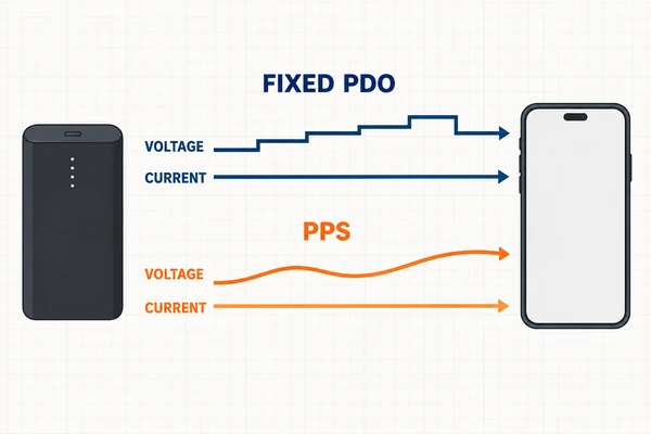
For fixed-voltage charging, a source advertises Fixed Supply PDOs. A PPS-capable source advertises a Programmable Power Supply Augmented PDO, or APDO, with an allowed voltage range and current limit. PPS lets the sink request voltage in small steps instead of choosing only from a set of fixed voltages. STMicroelectronics’ introduction to USB Type-C and USB PD describes PDO negotiation and PPS as part of USB PD operation.
Extended Power Range, or EPR, permits USB PD power levels above the earlier 100W ceiling. USB-IF describes EPR as supporting up to 240W over USB-C, with a maximum 48V and 5A contract. That does not mean every USB-C power bank, cable or connected device supports EPR. The product, controller, power stage, connector, cable and firmware must all match the claimed range. See the USB-IF EPR announcement.
For 2026 projects, the USB-IF document library lists USB PD Revision 3.2 Version 1.2, USB Type-C Release 2.5 and the Q3 2026 USB PD Compliance Test Specification. Record the edition used for development and certification instead of writing only “latest USB PD” in the purchase documents. The current files are available from the USB-IF document library.
Why must input and output fast charging be tested separately?
A power bank normally has two different PD roles.
When it charges a phone or laptop, it acts as a source. When the power bank itself is recharged, it acts as a sink. A bidirectional USB-C port can support both roles, but its output and input limits may be different. A specification that says “PD 45W” without identifying the direction is incomplete.
For every port, record:
| Port field | Example of a defined entry |
|---|---|
| Physical port | USB-C1 |
| Direction | Input and output |
| Maximum output | 45W under the stated PDO |
| Maximum input | 30W under the stated PDO or PPS range |
| Supported source PDOs | Exact voltage and current pairs read from the approved sample |
| Supported sink requests | Exact profiles the power bank can request from a charger |
| PPS support | Direction, voltage range, current limit and any restrictions |
| Shared-power rule | USB-C1 behaviour when USB-C2, USB-A or wireless output is active |
Treat “two-way fast charging” as a claim that needs two sets of results. Fast output does not prove fast input, and the reverse is also true.
What should be frozen before testing starts?
Fast-charging behaviour can change without any visible change to the housing. Freeze the tested configuration before collecting approval data.
The record should identify the model, SKU, sample number, cell model and lot, cell arrangement, PCBA revision, USB PD controller, power-stage components, firmware version, connector specification and included cable. Photograph the rating label and port markings. If a built-in cable is part of the product, identify its direction and rated power as well.
Firmware matters here. A supplier can change advertised PDOs, current limits, temperature derating or multi-port priority in code. If the firmware changes after sample approval, compare the source capabilities and repeat the affected functional and load tests.
The same rule applies to controller or converter substitutions. A component described as “equivalent” may negotiate differently, run hotter or recover from a fault in another way. Link every test report to the configuration it actually represents.
What equipment is needed?
A USB power meter is useful for a quick check, but an OEM approval programme needs more control.
| Equipment | What it is used for |
|---|---|
| USB-C PD protocol analyser or exerciser | Reads PDOs and APDOs, requests profiles and records negotiation messages |
| Programmable electronic load or PD sink | Applies a repeatable current or power load at the negotiated voltage |
| DC power analyser or calibrated meter | Logs voltage, current, wattage and delivered energy |
| Oscilloscope with a suitable probe arrangement | Checks transient response, ripple or abnormal transitions when these are part of the plan |
| Temperature logger or thermal camera | Records case and defined internal or component measurement points |
| Programmable USB-C PD source | Tests how the power bank behaves as a sink during recharge |
| Reference cables | Separates cable limits and voltage drop from product behaviour |
| Named consumer devices | Confirms interoperability with the intended phones, tablets and laptops |
Select instruments with the required voltage, current, bandwidth, accuracy and logging duration. Record model numbers, serial numbers and calibration status in the report. A low-cost inline meter can alter the connection or fail to expose the protocol details needed for diagnosis.
USB-IF publishes separate functional, source-power and USB PD compliance test documents and identifies approved test systems on its USB-C and Power Delivery testing page. Factory qualification is useful, but it is not a substitute for USB-IF certification when the project requires certified logo use or a formal compliance listing.
How should an OEM buyer test fast-charging output?
Start with an approved test matrix. Each row should name the sample, port, cable, requested profile, load, starting battery state, duration and pass criteria.
1. Read the advertised source capabilities
Connect a PD analyser or exerciser to each USB-C output. Capture the source capabilities exactly as advertised by the finished sample.
Compare the result with the product specification, label, manual, packaging and sales page. If the specification promises PPS but the analyser sees only fixed PDOs, the product does not meet that version of the claim. If a 65W value appears only on the packaging and no port can advertise or deliver it, stop the approval process and resolve the discrepancy.
Save the raw protocol capture. A typed list in a report is easy to copy from another model; the original capture is stronger evidence.
2. Request and load every claimed fixed profile
Negotiate each fixed PDO one at a time. Confirm that the source reaches the requested voltage, remains within the agreed tolerance and supplies the specified current without an unexpected reset or fallback.
Raise the load according to the written method rather than jumping blindly to the highest current. Hold the rated operating point for the agreed duration and log the result. Repeat the test on every port that carries a wattage claim.
Use measured values in the report:
Output power (W) = measured voltage (V) × measured current (A)
For example, 19.7V at 2.24A is approximately 44.1W. Record the actual voltage and current instead of rounding the observation to a 45W pass without applying the approved tolerance.
3. Check PPS as a range, not one convenient point
PPS testing should confirm the advertised APDO range, current limit and voltage transitions. Request several points across the approved range, including the boundaries and intermediate values. Check that the response is monotonic and remains within the tolerance required by the applicable specification and project plan.
PPS also needs a time-based check with a compatible sink or device. The requested voltage may change as the connected battery charges. A power bank that responds at one PPS setting but drops the contract during a longer charging session is not fully validated.
Texas Instruments’ PMP40441 power-bank reference design illustrates the distinction between fixed USB PD voltages and programmable PPS output. For formal compliance work, use the current USB PD specification and CTS rather than copying the ranges of a reference design into a different product.
4. Test sustained power at several battery levels
The converter has an easier job when the internal battery is full. Near the lower discharge limit it may draw more current from the cells to maintain the same USB output. That can raise losses and temperature or trigger an earlier power reduction.
Run the claimed output at agreed state-of-charge checkpoints. A practical engineering plan might include a high, middle and low battery level, but the buyer and laboratory should define exact starting conditions. Continue long enough to distinguish a momentary peak from stable operation.
Record any planned derating. If the product is allowed to reduce from 65W to 45W below a stated battery level, that rule belongs in the specification and user information. An undisclosed reduction is a failed claim, not a footnote to add after testing.
5. Check transitions, disconnects and recovery
A stable steady-state reading does not cover normal use. Test connection, disconnection, cable reversal and repeated attachment. Change between supported profiles with controlled equipment and observe whether the output reaches the new contract cleanly.
Include recovery after over-current protection, output short-circuit testing under the laboratory’s approved safety method, a sink that stops requesting power and a low-power device that draws only a small current. Record whether recovery is automatic, requires a button press or requires the cable to be reconnected.
Protection tests should follow the product safety plan. Do not improvise fault conditions on an unprotected desk fixture.
6. Test every advertised multi-port combination
Multi-port power banks often share one conversion stage or a limited total power budget. The maximum printed beside one port may apply only when that port is used alone.
Create a port-allocation table for each supported combination:
| Active outputs | USB-C1 | USB-C2 | USB-A | Wireless | Total limit | Reconnection behaviour |
|---|---|---|---|---|---|---|
| C1 only | Test result | Not active | Not active | Not active | Measured total | Record |
| C1 + C2 | Test result | Test result | Not active | Not active | Measured total | Record |
| C1 + A | Test result | Not active | Test result | Not active | Measured total | Record |
| C1 + wireless | Test result | Not active | Not active | Test result | Measured total | Record |
The table above is a structure, not a set of target values. Fill it with the approved model’s power-allocation rules.
Check what happens when the second device is attached after the first device has already negotiated a high-power contract. Some products briefly interrupt all outputs and renegotiate; others preserve one port and limit the new connection. Either behaviour can be acceptable if it is safe, repeatable and accurately described.
USB-IF now publishes a Shared Capacity Charger Interoperability Compliance Test Specification for products that distribute available power across ports. The current file is listed in the USB-IF document library.
How should input fast charging be tested?
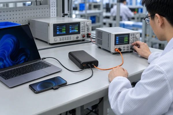
Discharge or condition the sample to the starting level defined in the test plan. Connect it to a programmable PD source or an approved reference charger through the specified cable. Capture the power bank’s sink request and record input voltage, current, power, battery level, time and temperature throughout the recharge.
Check more than the initial peak. Input power normally changes as the battery fills and the charge controller moves through its charging stages. The report should distinguish maximum negotiated power, maximum measured input power, average power over a defined interval and total time to the stated charge endpoint.
Repeat with each supported input port and built-in cable. If the power bank supports simultaneous input and output, test pass-through operation only when that feature is claimed or approved. State the allowed port combinations, total power limits, battery behaviour and thermal criteria. Do not assume that a bidirectional USB-C port automatically permits every pass-through arrangement.
Why is device compatibility testing still necessary?
A protocol analyser proves what the port advertises. It cannot represent every phone, laptop, cable and firmware combination in the target market.
Build a small compatibility matrix around the intended customers rather than collecting random devices from the office. A useful set may include:
- A current USB PD phone that uses fixed profiles.
- A PPS-capable Android phone from a target brand.
- A tablet that can hold a mid-power load for longer than a phone.
- A laptop near the power bank’s claimed output class.
- A low-power accessory such as earbuds or a watch charger.
- A legacy USB-A device if the product advertises an older fast-charging protocol.
- The included cable and at least one approved reference cable of each required power class.
Record the device model, operating-system version, starting battery level, cable and observed charging mode. A phone may draw less than the power bank’s maximum because the phone chooses the contract, its battery is nearly full or it is limiting power due to temperature. The result should be reported as an observed combination, not used to rewrite the power bank’s electrical rating.
Do not describe a proprietary USB-A mode as USB PD. List it by its actual protocol or by tested voltage and current when the trademark or licence position is unclear.
How should cables be controlled?
The cable is part of the power path. Voltage drop, current rating, connector condition and electronic marking can affect the negotiated contract.
For power above 60W, use an appropriate cable rated and identified for the required power level. USB-IF’s current certified cable logo programme uses 60W and 240W power markings. See the USB-IF cable and connector guidance. A cable marked 240W does not make the power bank a 240W product; it only removes one possible bottleneck when the rest of the system supports the contract.
Record the manufacturer, model, length, power rating and electronic-marker information for every reference cable. Inspect built-in cables separately for connector fit, strain relief and repeated bending because a cable failure can become a full product return.
YULIDA’s guide to choosing a power bank with a built-in cable covers the mechanical and sourcing checks that sit alongside the electrical test.
What thermal and protection results should be recorded?
Measure temperature at defined locations while the sample delivers and receives the claimed power. Typical points include the enclosure above the power stage, the cell area, the connector and the cable termination. Keep the ambient condition and airflow arrangement consistent.
There is no useful universal surface-temperature limit for every power bank test. The pass criteria must come from the product design, component ratings, applicable safety requirements and approved use conditions. Record the actual temperature curve and any power reduction, shutdown or oscillation.
Watch for behaviour that a single peak-temperature number can hide:
- Repeated PD renegotiation as the unit warms.
- Cycling between full output and thermal shutdown.
- A connector hotspot caused by contact resistance.
- Different results with the enclosure assembled.
- One sample running materially hotter than the rest.
- Failure to recover after the temperature returns to the allowed range.
USB-IF compliance updates state that, from January 2025, power banks capable of wireless charging must undergo the Source Power Test Requirements evaluation with the wireless function fully loaded for the relevant compliance programme. This matters for combined-output designs because the wireless load can change the available USB-C power and thermal result. See the USB-IF Power Delivery compliance updates.
How is conversion efficiency checked?
Efficiency helps explain heat and usable energy, but it should be measured at a defined battery condition and output profile.
Conversion efficiency (%) = USB output power (W) ÷ battery-side input power (W) × 100
Battery-side measurement may require an instrumented engineering unit or approved fixture. If the finished enclosure does not permit a valid battery-side measurement, do not estimate efficiency from the printed cell capacity and a USB meter. Report USB output energy separately using the method in YULIDA’s guide to testing power bank capacity.
For engineering comparison, map efficiency at several loads rather than quoting only the best point. Low load, typical phone charging, rated output and a mid-battery condition often tell a more useful story than one laboratory maximum.
What should the acceptance criteria say?
Write the requirement so another laboratory can repeat it without asking the supplier what the buyer meant.
| Field | Example of a defined requirement |
|---|---|
| Samples | Five finished units selected from identified pilot-production stock |
| Configuration | Approved cell, PCBA, PD controller, firmware, enclosure and cable revisions |
| Test environment | Stated ambient range and airflow condition |
| Source capabilities | Every port advertises only the approved PDOs and APDOs |
| Fixed-profile test | Each claimed profile meets the agreed voltage, current and duration criteria |
| PPS test | Approved APDO range, current and selected transition points pass |
| Sustained power | Claimed output is maintained for the stated time at defined battery levels |
| Multi-port operation | Each listed port combination follows the approved allocation table |
| Input charging | Correct sink request, recharge time, temperature and endpoint behaviour |
| Compatibility | Required device and cable combinations connect and remain stable |
| Protection | Defined trips and recovery behaviour operate without damage or uncontrolled restart |
| Physical condition | No swelling, leakage, case deformation, connector damage or abnormal odour |
| Decision rule | Allowable failures and treatment of interrupted or invalid tests |
| Evidence | Raw protocol captures, electrical logs, thermal records, photographs and signed report |
Replace every example with model-specific values. A useful statement might read:
USB-C1 shall advertise the approved source PDO and PPS APDO set. Each of five finished units shall negotiate and sustain the specified output at the defined high, middle and low battery states using the approved cable and test method. Multi-port operation shall follow the signed power-allocation table. No unit may show an unexplained reset, unstable renegotiation, protection fault or physical damage.
The paragraph above is a format, not a universal pass limit. Attach the actual profile table, duration, tolerances and temperature criteria to the specification.
What should be included in the test report?
A report should make the result traceable to one configuration and one set of samples. Include:
- Buyer, supplier, project and test-laboratory details.
- Model, SKU, sample IDs, build date and production or pilot lot.
- Cell model and lot, PCBA revision, controller and firmware version.
- Label, packaging and manual claims reviewed.
- Instrument and cable identification with calibration status.
- Test conditions, connection diagrams and state-of-charge method.
- Source-capability and negotiation captures for each applicable port.
- Voltage, current, power, energy and temperature logs.
- Multi-port allocation and device-compatibility results.
- Photographs before and after testing.
- Deviations, failures, operator interventions and final disposition.
Keep the raw data with the signed summary. Screenshots pasted into a report are hard to reanalyse when a field complaint appears six months later.
Which factory checks belong in mass production?
Full compliance and long-duration load tests do not need to run on every unit. Production control should confirm that shipped goods still match the approved design.
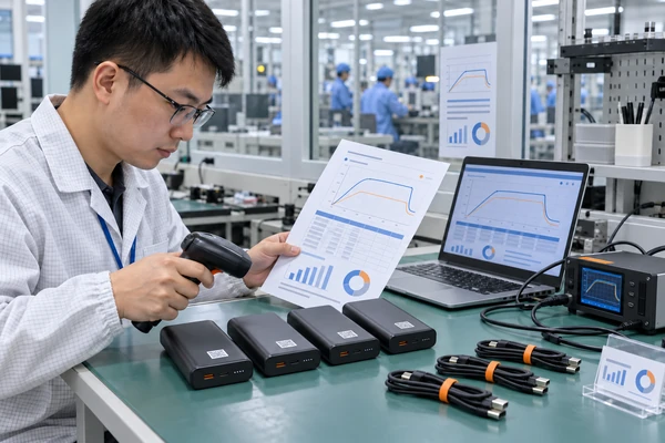
Depending on the model and risk, the control plan can include incoming checks for the PD controller and power-stage components, firmware verification, automated reading of advertised profiles, sampled load tests, connector inspection and finished-unit charging checks. Multi-port and PPS checks can be included in lot sampling when those functions drive the product claim.
Define the sample size and failure action before production. If a lot sample advertises the wrong PDO set, do not treat it as one isolated cosmetic defect. Hold the affected lot, check firmware and component traceability, determine the scope and repeat the agreed verification after corrective action.
Review these controls alongside YULIDA’s power bank quality-control process and the approved power bank product specification.
Common mistakes in power bank fast-charging approval
Approving the highest number on a display
A peak wattage reading does not prove the profile, duration or repeatability. Keep the negotiated contract and time-based log.
Testing only at 100% battery
Repeat the claimed load at defined lower states of charge. Converter stress and available output can change as cell voltage falls.
Assuming every port has the same rating
Test and label ports separately. The USB-C input/output port, second USB-C port, USB-A port and built-in cable may use different protocols and limits.
Adding all port ratings together
Individual maxima do not necessarily equal simultaneous total output. Approve a combination table.
Using an unknown cable
An unsuitable or damaged cable can block a high-power contract or add voltage drop. Identify and control reference cables.
Treating a chipset datasheet as a finished-product result
The controller may support features the firmware or power stage does not implement. Test the assembled SKU.
Calling a factory check USB-IF certification
Internal tests support product development and purchasing decisions. Certified logo use requires the applicable USB-IF compliance and licensing process. USB-IF states that products must pass the relevant compliance testing to qualify for certified logo use; see the USB-IF logo licence page and certified product search.
Frequently asked questions
1. Does a USB-C port always support fast charging?
No. USB-C describes the connector. Check the advertised USB PD capabilities, measured output and product documentation.
2. What does 20W, 45W or 65W mean on a power bank?
It should identify a maximum output power for a specific port and operating condition. The specification still needs the supported voltage and current profiles, duration, battery-state limits and multi-port rules.
3. Is PPS better than fixed USB PD?
PPS gives a compatible sink finer control of the requested voltage. Whether it improves charging speed or temperature depends on the phone, cable, power bank implementation and charging state. Test the target device rather than assuming a PPS logo guarantees a particular result.
4. Why does a phone draw less power than the power bank rating?
The connected device requests the power it can use. Battery level, temperature, cable capability, device firmware and active outputs can all reduce the observed value.
5. Should fast charging be tested with phones or an electronic load?
Use both. Controlled equipment measures repeatable electrical performance; named consumer devices test real interoperability.
6. Does a 100W USB-C power bank need a special cable?
Use a cable with the required current, power rating and electronic marking for the intended contract. Do not rely on an unverified cable supplied with another product.
7. Can two USB-C ports each deliver their printed maximum at the same time?
Only if the approved power-allocation table says so and testing confirms it. Many products share a lower total power budget.
8. Does fast input charging mean the power bank will recharge at maximum wattage until full?
No. Negotiated and measured input power usually changes during the charging cycle. Compare recharge time and the full power curve under defined conditions.
9. Can a supplier use one fast-charging report for several SKUs?
Only when the buyer can show that the tested configuration represents those SKUs for the claimed functions. Different cells, PCBA revisions, port layouts, firmware or built-in cables may require separate evidence.
10. Is an internal factory test the same as USB-IF certification?
No. Factory testing supports design and quality control. USB-IF certification follows its own compliance programme, approved test requirements and logo rules.
Send the fast-charging matrix with the OEM RFQ
Tell the supplier which devices the power bank must charge, the required output and input power, the ports that carry each claim, whether PPS or EPR is required, and which multi-port combinations users will rely on. Add the approved cable, temperature criteria, sample plan and evidence package.
During sample approval, compare the analyser capture with the label, manual and packaging. Freeze the PCBA and firmware with the golden sample. Production checks can then look for changes instead of trying to rediscover the intended behaviour after shipment.
Send YULIDA the target capacity, USB-C PD and PPS requirements, device list, port configuration, battery specification and order quantity. The team can review suitable power bank platforms and prepare a model-specific test and quotation plan. Contact YULIDA about an OEM power bank project.
Official sources and verification
These primary sources support standards, compatibility, safety, or transport statements discussed in this article. Confirm the current requirement for the exact product model and destination market.
- USB Implementers Forum — USB Type-C and USB Power Delivery specifications and guidance.
- USB Implementers Forum — USB Type-C and USB Power Delivery specifications and guidance.
- USB Implementers Forum — USB Type-C and USB Power Delivery specifications and guidance.
- USB Implementers Forum — USB Type-C and USB Power Delivery specifications and guidance.
- USB Implementers Forum — USB Type-C and USB Power Delivery specifications and guidance.
- USB Implementers Forum — USB Type-C and USB Power Delivery specifications and guidance.
