





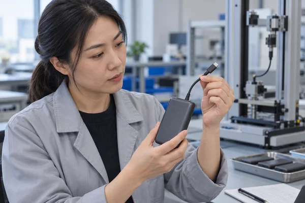
How to Test Built-In Power Bank Cable Durability Before a Bulk Order?
An attached charging cable is convenient until it fails. On a power bank, that can turn a small cable fault into a return of the whole product. Before approving an OEM order, test the finished unit at the places people actually stress it: the cable exit, the plug, any storage channel or retractor, and the connection while charging. Record electrical performance before and after the mechanical tests. A cable that still looks intact but drops power when moved has not passed.
There is no useful universal “durable for 10,000 bends” claim without a method. Bend angle, radius, speed, load, sample size and pass rule change the meaning of that number. Put those conditions in the approved specification, then use the same plan on the production-intent sample and the relevant shipment samples.
Why does an integrated cable need its own test?
A detachable cable can usually be replaced without replacing the power bank. An integrated cable is part of the assembled product. Its failure may be in the conductor, the plug, the strain relief, the internal connection or the mechanism that stores it. A normal output-capacity test may miss all of those faults if the cable lies still throughout the run.
The product design changes the likely stress point. A short fixed lead bends at the housing exit. A retractable lead adds a moving mechanism and an end stop. A strap cable may be pulled when someone picks up the unit. YULIDA’s built-in cable buyer guide identifies bending, pull, insertion and charging under load as separate checks. This article turns those checks into an approval plan.
For USB-C, the USB-IF Type-C connector and cable-assembly compliance document covers mechanical, environmental and electrical criteria for connectors and passive cable assemblies. That is useful evidence for a specified component. It does not, by itself, show how a cable anchor, storage slot or retractor behaves inside a particular finished power bank. Test those assemblies on the product you intend to buy.
Define the cable before setting a cycle count
The buyer and factory should be able to identify the same configuration without relying on a catalogue photo. Record the buyer SKU and factory model, capacity variant, cable drawing and length, connector type, cable supplier or controlled part number, PCBA revision, firmware where relevant, and the production-intent sample. State whether the cable is output-only, input-only or bidirectional. Include its claimed voltage, current and charging protocol for each direction.
Add the mechanical details that influence the test: cable exit geometry, strain-relief material, plug overmould, storage path, allowed extension length and whether the cable is intended to support the weight of the power bank. A strap-shaped cable is not automatically a rated carrying handle. The approved drawing and user instructions need to settle that point.
Le A217 product page describes a strap-style Type-C cable but asks buyers to verify cable durability on the approved sample. The AJ07 retractable-cable model raises a different question: how many extension and retraction cycles can the complete mechanism survive under an agreed method? Neither design should inherit a pass limit from a visually similar product.
How should bend and pull tests be run?
Bend at the points that fail in use
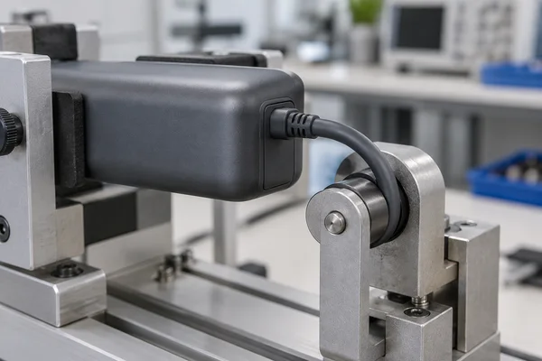
Inspect the cable first and record a charging baseline. Then use a fixture that bends the same location in a repeatable way, usually near the housing exit and again near the plug. State the angle, bend radius, cycle rate, number of cycles and cable orientation. If the lead can bend in more than one plane during normal use, include the relevant directions. Photograph the fixture and the cable position; “bent 5,000 times” is not a reproducible record on its own.
At defined intervals, stop to check the jacket, strain relief and electrical behavior. Look for whitening, cracks, exposed conductor, a loosened overmould or intermittent output. The question is whether the cable still performs its intended job after the specified wear, not whether it merely remains attached. If a tester monitors continuity while cycling, record the detection threshold and log interruptions rather than writing “no issue observed.”
Keep pull and carrying tests separate
A pull test loads the cable or plug along a defined direction for a stated force and duration. The fixture must show what is clamped and where the force is applied. Pulling the plug body tests a different joint from pulling the cable at the housing exit. Run the tests that correspond to foreseeable handling, and inspect both the external joint and the function afterward.
If a strap cable is advertised for carrying, add a handling test based on the product’s weight and stated use. If it is not a handle, make that clear in the manual and avoid suggesting it in product imagery. Do not improvise destructive pulls on charged lithium-battery products; qualified personnel should use a controlled fixture and stop rules appropriate to the sample.
What changes for plugs, storage slots and retractors?
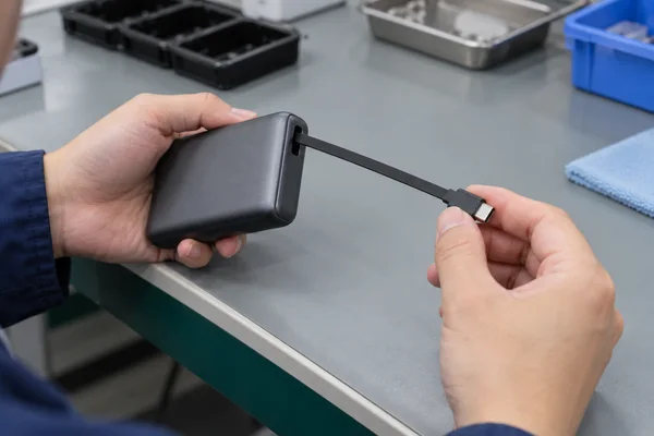
Repeated mating tests the plug’s fit and wear. Specify the reference receptacle, insertion alignment, cycle count, speed and force measurement points. After cycling, check retention, visible damage, charging stability and whether the plug still fits the target devices. A loose connector can pass a brief power test when held still and fail in a pocket or bag.
For a fixed cable, include removal from and return to its storage channel if users do that every day. Check whether the channel pinches the jacket or presses on the plug. For a retractable design, log full and partial extensions, release action, end-stop behavior, retraction force, jams and the remaining exposed length after each test interval. Cable twisting and pulling beyond the stop need their own agreed handling rules. The AJ07 page specifically calls for buyers to confirm cable length, pull-and-retract life and connector durability on the production sample.
Do not roll every mechanical action into one grand “cycle” number. A plug insertion, a cable bend and a retraction are three different events. Keep their counts and failure criteria separate.
What electrical checks should follow mechanical stress?
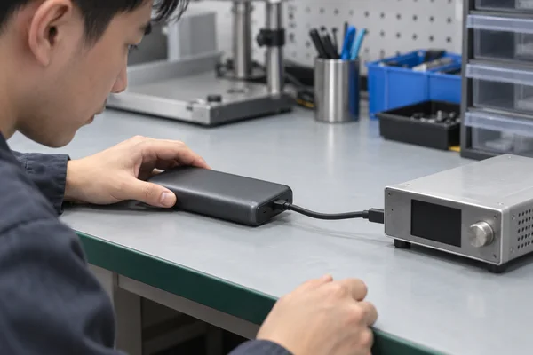
Test electrical performance before the wear sequence, at agreed checkpoints and at the end. Use the same charger or load, battery state, cable position, ambient condition and measurement point so the results are comparable. A suitable meter and protocol analyser can show whether the built-in lead still negotiates the claimed mode and sustains it under load. Record voltage at the output connector, current, negotiated profile, power, temperature and any disconnect or renegotiation.
Cable resistance matters. If voltage at the connector falls more after cycling under the same current, investigate the cable and its joints. Measure at defined points; a voltage reading at an external USB port does not automatically reveal the loss along an attached cable. The buyer should also compare the built-in cable with any separate port, while remembering that the two paths may have different ratings or controller behavior. The fast-charging test guide explains how to log claimed USB-C profiles on the finished product.
An intermittent fault may appear only when the lead moves. If the approved lab plan includes an under-load movement check, use protected equipment and record the cable position and event trace. Do not turn an informal hand wiggle into a pass/fail test. After a failure, keep the failed sample and its original log; a later successful retest should not erase the event.
How should a buyer write pass and fail criteria?
Agree limits before the factory runs qualification. The right values depend on cable construction, use case and the current applicable connector requirements. The specification should give a method and a result for each failure mode, not one unsupported life claim.
| Contrôle | Define before testing | Justificatifs à conserver |
|---|---|---|
| Bend life | Bend point, radius, angle, rate, cycles and acceptable damage | Fixture photo, interval observations and post-test electrical log |
| Pull strength | Grip points, direction, force, duration and allowable movement | Force trace, before/after photos and function check |
| Plug wear | Reference receptacle, insertion procedure, cycles and retention rule | Force measurements, fit inspection and charging result |
| Storage or retraction | Extension length, operating sequence, cycles and jam rule | Cycle log, stop-point photos and final function test |
| Charging after wear | Direction, profile, load, measurement point and allowed change from baseline | Meter or protocol log, temperature and failure events |
Qualification and shipment inspection have different jobs. A longer or destructive life test belongs to controlled development or qualification samples. Finished-lot inspection can use an agreed sampling plan and appropriate non-destructive checks, backed by the approved qualification record. State what happens if a sample fails: hold the affected lot, identify the cause, define rework or replacement, and repeat the relevant tests. Do not quietly lower the limit after seeing the results.
Le product-specification guide treats durability, test method and acceptance rules as part of a controlled SKU specification. Its processus de contrôle qualité includes cable and connector checks across incoming, assembly and final inspection. Ask which of those checks apply to the exact cable arrangement in your order, and request the corresponding records rather than a generic “tested” statement.
What should arrive with the production lot?
Keep the approved sample ID and test method with the purchase order. The shipment record should identify the SKU, production lot, cable part or supplier lot, connector revision, relevant PCBA or firmware revision, sampled unit IDs, test results and disposition of failures. If the cable supplier, plug, jacket, strain relief or retractor changes, decide which qualification tests must be repeated before the change enters production.
This is particularly important on a multi-cable model. YULIDA’s AJ41 product page lists several integrated outputs and asks buyers to verify each connector definition and durability. One cable passing does not establish the condition of the others. Record results by cable position and function, then match them to the finished lot.
Questions fréquentes
1. How many bend cycles should a built-in power bank cable survive?
There is no single number that fits every design. Agree the cycle count and fixture method for the exact SKU, including bend point, radius, angle and speed. Pair the mechanical result with a charging test after cycling. Without those details, a quoted cycle count is hard to compare or enforce.
2. Does a USB-C connector test prove the whole built-in cable is durable?
No. Connector evidence can address the plug or receptacle under its stated test method. The finished power bank adds a cable anchor, enclosure and sometimes a storage or retracting mechanism. Verify those on the assembled product. Check the applicable USB-IF documents for the connector requirements relevant to the selected version.
3. Can a strap-style charging cable be used to carry the power bank?
Only if the supplier has specified and validated that use for the finished model. Confirm the intended handling in the drawing and user instructions, then test the assembled anchor and cable under an agreed load. A strap-like appearance alone is not evidence of a carrying rating.
4. Why test charging after the cable still looks intact?
A conductor or joint can become intermittent before the jacket visibly breaks. Compare the same charging mode before and after wear, and log voltage, current and disconnects. An attached cable that no longer delivers its approved function fails even if the exterior looks acceptable.
5. Should every power bank receive a destructive cable-life test?
No. Use controlled samples for qualification and an agreed sampling and functional-inspection plan for production. Record which units were tested, the lot they came from and what happened to failed units. The sampling plan should be approved before manufacturing, not chosen after a failure.
Sources officielles et vérification
Ces sources primaires étayent les informations de cet article sur les normes, la compatibilité, la sécurité ou le transport. Vérifiez les exigences actuelles pour le modèle précis et le marché de destination.
- USB Implementers Forum — Spécifications et recommandations USB Type-C et USB Power Delivery.
- USB Implementers Forum — Spécifications et recommandations USB Type-C et USB Power Delivery.
