







USB-C PD Power Bank Specifications: Profiles, PPS and Buyer Checklist
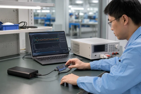
To verify USB-C PD power bank specifications, check each port’s input/output role, fixed PDOs, PPS support, cable rating and shared-output allocation. Then test sustained power and temperature on the production-equivalent sample. A headline wattage alone cannot establish compatibility or performance; keep the agreed limits and model-specific test records before approving an OEM order.
USB-C identifies a connector. USB Power Delivery defines communication and power negotiation over that connection. A buyer has to verify the port role, advertised source capabilities, accepted input profiles, cable capability, multi-port allocation and behaviour under load. This guide turns those checks into an OEM approval process.
USB-C PD buyer acceptance checklist
A voltage and current table is a starting point, not proof. Ask the supplier for evidence from the production-equivalent power bank:
| Item to verify | Evidence to request | Acceptance basis |
|---|---|---|
| Port and cable roles | Separate input and output ratings for each connection | Directions and modes match the signed specification |
| Fixed PDOs and PPS | Source-capability logs, accepted contracts and PPS APDOs where claimed | Required profiles negotiate with the agreed target devices |
| Cable capability | Supplied-cable rating, identity data where applicable and load results | Cable supports the required current without exceeding agreed limits |
| Shared output and pass-through | Per-port allocation for each supported combination | Total power, interruptions and limitations match the approved matrix |
| Sustained performance | Time-based voltage, current, power and temperature logs | Meets agreed duration and limits at specified battery states and ambient temperature |
| Certified USB claims | Finished-product listing and applicable logo-license evidence | Certification and marks match the exact product being supplied |
The evidence should identify the model, PCBA revision, firmware, cable and test conditions. Attach it to the approved product specification, or send YULIDA your required charging matrix for model review.
USB-C, wattage and USB PD are three different claims
A USB-C receptacle tells you the physical interface. It does not tell you whether the port is input or output, which charging protocol it uses, its maximum power or whether it carries data. The number printed beside it is also incomplete without a negotiated operating point.
Electrical power is calculated as:
Power (W) = Voltage (V) × Current (A)
For example, 9V × 2.22A is approximately 20W. That calculation does not identify USB PD. The same product may also support another charging method, and a row such as 12V/1.67A should not be labelled as a standard fixed USB PD profile without protocol evidence. Check the analyser record, controller specification and target-device result before naming PD, PPS or another protocol.
Define the power role of every connection
Power direction is no longer fixed under USB PD. A USB-C port can provide power as a source, receive power as a sink, or support both roles. Power banks often use one bidirectional USB-C port for recharging the battery and charging a device, but the two directions rarely have identical ratings.
| Connection | Questions for the supplier | Evidence to keep |
|---|---|---|
| USB-C input | Which fixed and PPS profiles can the power bank request? What is the maximum input? | Sink capability and successful charge contracts |
| USB-C output | Which profiles does the power bank advertise? How long can it sustain the maximum? | Source capabilities, load curve and thermal record |
| Bidirectional USB-C | How does the port decide direction? Can it reverse unexpectedly? | Role tests with representative chargers and devices |
| Built-in USB-C cable | Is it input, output or both? Does it support the same profiles as the receptacle? | Cable construction, analyser logs and bend tests |
Write each direction as a separate line in the specification. “USB-C: 65W” is too vague for quotation, sample approval or packaging.
Read the source capabilities instead of the headline wattage
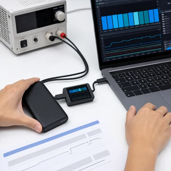
When a power bank acts as a source, it advertises the power options available to the connected device. The device requests one option, and the two sides form a contract. A protocol analyser can display the advertised PDOs, the selected request and later renegotiation.
Common Standard Power Range fixed source voltages include 5V, 9V, 15V and 20V. The current available at each voltage depends on the source design and declared power. A product does not need to offer the same current at every voltage, and a laptop will not take the headline power unless one advertised option matches what it can request.
| Claim to review | What the buyer should verify |
|---|---|
| 20W USB-C output | Advertised PDOs, successful contracts and sustained output at the claimed operating point |
| 30W or 35W output | Exact voltage/current combination, target-device compatibility and cable loss |
| 45W output | 20V capability where required, current limit, battery condition and temperature |
| 65W output | 20V/3.25A contract or another valid supported mode, suitable cable, sustained power and thermal behaviour |
Do not assume a phone will request 20V because the power bank offers it. The sink selects from compatible options, subject to its charging design and current operating state.
PPS needs an APDO and a working charging cycle
Programmable Power Supply, or PPS, allows a compatible sink to request intermediate voltage values within an advertised range. It is part of USB PD, but it is not present on every PD source or every PD sink. USB-IF describes certified fast chargers as supporting the PPS feature of USB PD.
For an OEM power bank, ask the analyser to show the PPS APDO, voltage range, maximum current and a successful PPS charging session with a target device. A controller datasheet that lists PPS capability does not prove that the finished firmware, power stage and cable work together correctly.
PPS source and PPS sink are different functions
A power bank can support PPS when charging a phone but use only fixed profiles when being recharged, or the reverse. Record both directions. If the packaging simply says “PPS”, buyers and users cannot tell which role the claim describes.
SPR and EPR should not be confused
USB PD Revision 3.1 expanded power delivery from the earlier 100W limit to as much as 240W over USB-C. USB-IF lists new 28V, 36V and 48V fixed levels for power up to 140W, 180W and 240W. These are Extended Power Range applications.
A 65W power bank remains in the Standard Power Range. Calling it “PD 3.1” does not make it faster, and buyers should not use a version number as a substitute for the actual source-capability table. If a project genuinely uses EPR, the power path, connectors, cable and compliance plan all need to support the higher-voltage range.
USB-IF updates the USB Power Delivery specification and its compliance procedures. Confirm the applicable base specification, test version and transition rules for the exact product and certification route. Check the official USB Power Delivery specification page before approving a version claim.
A 65W contract also depends on the cable
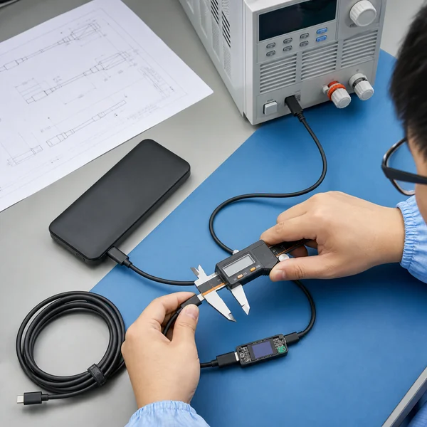
A 20V/3.25A output needs more than the 3A current supported by a basic USB-C to USB-C cable. Verify a 5A-capable electronically marked cable, its identity data, conductor design, connector quality and voltage drop. Test with the cable that will be supplied in the retail box.
USB-IF now uses 60W and 240W power markings for USB-C to USB-C cables in its compliance programme. This does not give an uncertified supplier permission to copy the protected logo. It does provide a useful distinction when the buyer specifies and verifies cable capability. The official USB-IF cable and connector guidance explains the current marking and test framework.
Test cable voltage drop and temperature
An e-marker does not repair thin conductors or weak connectors. Measure voltage at the load, inspect connector temperature and repeat insertion tests. For a bundled cable, record the supplier, drawing, conductor size, length, e-marker information where applicable, strain relief and approved sample.
Built-in cables require their own specification
A built-in Type-C cable may use the same controller as the receptacle but a different power path, current limit or firmware rule. It may support output only, or it may recharge the power bank as well. Never copy the receptacle rating to the cable without a separate test.
- Confirm input and output direction separately.
- Capture the advertised source profiles at the built-in connector.
- Test voltage drop and connector temperature at the maximum load.
- Specify bending, pull, twist, insertion and storage-channel checks.
- Verify whether using the cable disables or reduces another output.
- Match the cable claim across the product label, box and manual.
The built-in cable power bank sourcing guide covers the mechanical checks that sit beside protocol testing.
Input power and output power need separate curves
A power bank described as 65W may accept 65W input but provide only 30W output, or provide 65W output while recharging at a lower rate. State both directions. Then record how power changes with state of charge and temperature.
For input testing, use chargers and cables that support the requested profiles. Capture the initial contract, charging curve, maximum input, tapering behaviour, full-charge time and enclosure temperature. For output, use an electronic load or supported device and record voltage, current, power, duration, cut-off and battery state.
A single photograph of a meter at 65W says nothing about how long the product held that level. Keep the time-based log.
Do not add the maximum wattage of every port
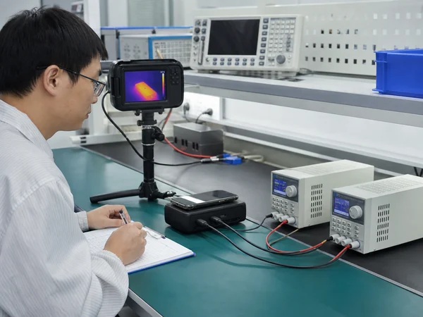
Multi-port power banks share a battery, converters and thermal limit. A USB-C port rated at 65W and a USB-A port rated at 22.5W do not automatically provide 87.5W together. Connecting a second device may reduce the USB-C port to a lower profile, redistribute current or restart both outputs.
| Test condition | Record for each output |
|---|---|
| USB-C alone | PDO/PPS contract, sustained power, temperature and cut-off |
| USB-A alone | Protocol, voltage, current and sustained power |
| USB-C + USB-A | Total power, allocation, renegotiation and restart behaviour |
| USB-C + built-in cable | Per-output power, priority and any disabled path |
| Wired + wireless | Shared capacity, coil load, temperature and throttling |
| All advertised outputs | Supported or prohibited combination and stable total output |
USB-IF publishes a shared-capacity test specification for USB-C and USB PD products. Its compliance update also states that wireless-charging power banks seeking USB PD certification must run the source-power test with wireless charging fully loaded. That detail matters for hybrid models that advertise their wired and wireless maximums side by side.
Pass-through charging needs a power-flow test
Pass-through charging means the power bank receives input while supplying another device. The phrase does not define the available output, whether the internal battery is charging, which port has priority or how heat is managed.
Draw the required power flow before testing. State the input charger, output device or load, allowed ports, battery state and expected allocation. Watch for repeated renegotiation, output interruption, battery cycling, rising temperature and a mismatch between the display and the actual current direction. If pass-through use is not supported, the manual and packaging should say so plainly.
Use a protocol analyser and an electronic load for different jobs
A protocol analyser shows communication: advertised capabilities, requests, accepted contracts, resets and role changes. An electronic load checks the power stage under controlled current or power. A USB power meter can help with routine checks, but a small display is not a complete protocol or compliance test.
| Tool | Useful evidence | What it cannot prove alone |
|---|---|---|
| PD protocol analyser | PDOs, APDOs, requests, contracts and resets | Sustained thermal performance or battery capacity |
| Electronic load | Voltage stability, current limit, output curve and cut-off | Correct protocol messages without analyser data |
| Power meter | Quick voltage, current and energy observations | Full compliance or accurate protocol decoding in every case |
| Thermocouples or thermal camera | Temperature location and trend | Protocol support or electrical safety by themselves |
| Target devices | Practical interoperability and charging behaviour | Coverage of all devices or specification compliance |
Use calibrated equipment where the result controls acceptance. Save raw logs and record instrument model, firmware, connection diagram, cable, ambient temperature and sample identity.
Maximum output must be sustained safely
Test maximum power long enough to see thermal throttling, voltage drift and low-state-of-charge behaviour. A compact power bank may hold 65W while the battery is full and cool, then reduce output as cell voltage falls or the converter heats up. That reduction may be intentional protection, but the product claim and user instructions should reflect real behaviour.
- Start at defined battery states, such as full, mid-level and low.
- Record ambient temperature and the hottest measured locations.
- Log output voltage, current and power over time.
- Note throttling, shutdown, restart and recovery conditions.
- Repeat with the supplied cable and a suitable reference cable.
- Check the final enclosure material, firmware and production cell.
The broader power bank quality test checklist explains how to combine protocol checks with capacity, conversion-efficiency and protection testing.
Test target devices, but do not call the result universal
A 65W laptop, a PPS phone and a handheld game console can request different profiles from the same source. Cable identity, device battery state, temperature and firmware also affect the observed power. Test the models that matter to the buyer’s market and record the result as a compatibility matrix.
A successful test with one laptop supports a statement about that configuration. It does not prove “works with all laptops”. Use precise packaging language such as the supported maximum output and tested profiles, followed by a normal compatibility qualification where needed.
USB-IF certification and factory tests are not the same
Factory analyser logs are useful for model approval and production control. They do not turn a product into a USB-IF certified product. USB-IF certification uses the applicable compliance programme and approved test procedures. Products qualified to bear certified USB logos are listed through the USB-IF product system.
USB-IF states that certified logos may be used only with products that passed the relevant compliance testing and are on the Integrators List, with the required trademark licence in place. Do not copy a wattage logo from another product or treat a controller certificate as finished-product certification. Check the official USB-IF logo licence guidance and certified product search.
Match the claim across the label, box, manual and listing
Once the electrical behaviour is approved, compare every public claim with the final test matrix. The product label needs readable input and output ratings. The retail box can explain the maximum port and cable power. The manual should show port direction, supported combinations and pass-through limits. The online listing must use the same numbers.
A common mistake is to print “PD 65W” on the front while the rating label lists only 5V, 9V and 12V options. Another is to put one 65W badge beside three outputs without saying which interface provides it. The power bank label and packaging checklist covers the artwork approval process.
Documents to request before sample approval
- controlled product specification with each port and cable direction;
- controller and power-path part numbers or an approved functional specification;
- source PDO and PPS APDO captures for every output path;
- sink contract records for the claimed input modes;
- single-output and simultaneous-output test matrix;
- sustained-load, ripple, voltage-stability and temperature records;
- supplied-cable drawing, rating, e-marker data where applicable and durability tests;
- target-device compatibility results;
- USB-IF test and listing evidence if certification or certified logos are claimed;
- approved label, packaging and manual revisions.
Put these records beside the approved sample. If the factory later changes the PD controller, power stage, firmware, connector, cable or battery cell, review the affected tests before production continues.
A copy-ready USB-C PD specification table
Use this structure in the RFQ and signed specification. Replace every blank with a measured or approved value.
| Field | Required entry |
|---|---|
| USB-C port role | Input, output or dual-role power |
| Maximum input | Watts plus all accepted fixed and PPS profiles |
| Maximum output | Watts plus all advertised fixed PDOs and PPS APDOs |
| Built-in cable | Direction, profiles, maximum current, length and construction |
| Supplied detachable cable | Power rating, current capability, e-marker and approved model |
| Multi-output allocation | Per-output and total power for each supported combination |
| Pass-through | Allowed input/output combination, allocation and limitations |
| Sustained output | Duration, starting battery state, ambient temperature and acceptance limit |
| Target devices | Models, cables, negotiated profiles and observed behaviour |
| Evidence revision | Sample ID, PCBA, firmware, test date and approver |
The power bank RFQ guide provides the rest of the product, battery, enclosure, packaging and compliance fields.
Red flags in a PD power bank quotation
- The quotation says “Type-C PD” but gives no voltage and current profiles.
- The headline wattage is the sum of unrelated port maximums.
- A 12V calculation is treated as automatic proof of USB PD.
- Input power and output power are mixed in one line.
- PPS is listed without an APDO capture or target-device session.
- The 65W sample is tested with a cable that will not be supplied.
- There is no simultaneous-output table for a multi-port model.
- The maximum is shown for a few seconds with no thermal or time log.
- A certified USB logo appears without model-level listing and licence evidence.
- The factory can replace the controller or cable without written approval.
One missing record may be easy to correct. Several missing records usually mean the product specification is not ready for a purchase order.
Approve the production sample, then freeze the configuration
Run the agreed protocol, load and compatibility tests on a sample that uses the intended battery cell, PCBA, firmware, enclosure, connectors and cables. Sign the specification and keep the logs with the sample record. The power bank sample approval checklist explains how to control that reference through mass production.
For incoming production and pre-shipment inspection, select representative units and repeat the critical source profiles, maximum load, multi-output allocation and cable checks. A controller substitution can change protocol behaviour without changing the outside appearance.
Frequently asked questions about USB-C PD power banks
1. Does a USB-C port mean the power bank supports PD?
No. USB-C describes the connector. Confirm USB PD through the advertised source or sink capabilities, protocol negotiation and applicable test evidence for that port.
2. Does 9V/2.22A prove 20W USB PD?
It proves that the two printed numbers multiply to about 20W. It does not identify the charging protocol. Use a PD analyser to confirm that the profile is advertised and that a compatible sink forms the expected contract.
3. What is the difference between PD and PPS?
USB PD can use fixed voltage options. PPS is a programmable mode within USB PD that lets a compatible sink request intermediate voltages inside an advertised APDO range. Both the source and sink must support PPS for that mode to operate.
4. Why does a 65W power bank charge some laptops more slowly?
The laptop may request a profile the power bank does not offer, the cable may limit current, or the source may reduce power because of temperature, battery state or simultaneous use. Compare the laptop requirement with the analyser capture and sustained-output result.
5. Can a 65W USB-C port and 22.5W USB-A port deliver 87.5W together?
Only if the product specification and measured simultaneous-output test confirm that allocation. Most multi-port designs share a total power budget, so each output may fall to a lower level when used together.
6. Is a protocol-analyser screenshot enough for OEM approval?
No. Keep analyser logs, but also test sustained power, voltage stability, temperature, cable performance, target-device compatibility and multi-output behaviour. The evidence must identify the final sample, PCBA and firmware.
Official USB-IF references
- USB Charger and USB Power Delivery overview
- USB Power Delivery base specification page
- USB Type-C and Power Delivery testing index
- USB-IF Power Delivery compliance updates
- USB cable and connector compliance guidance
- USB-IF logo licence and usage guidance
Specifications and compliance procedures change. Confirm the current version and certification route for the exact product rather than copying a test plan from another controller or power bank.
Send YULIDA the required charging matrix
For an OEM or ODM project, send the target devices, required input and output profiles, PPS requirement, simultaneous-use combinations, supplied cable and order quantity. YULIDA can review the requirement against an existing power bank platform or a deeper PCBA and firmware project.
YULIDA’s OEM Standard service starts at 500 pieces, Light Customization at 1,000 pieces and Deep ODM at 2,000 pieces. The selected model and written development scope determine the applicable tier. Review the OEM/ODM service scope or request a quotation for your approved charging requirements.
Official sources and verification
These primary sources support standards, compatibility, safety, or transport statements discussed in this article. Confirm the current requirement for the exact product model and destination market.
- USB Implementers Forum — USB Type-C and USB Power Delivery specifications and guidance.
- USB Implementers Forum — USB Type-C and USB Power Delivery specifications and guidance.
- USB Implementers Forum — USB Type-C and USB Power Delivery specifications and guidance.
- USB Implementers Forum — USB Type-C and USB Power Delivery specifications and guidance.
- USB Implementers Forum — USB Type-C and USB Power Delivery specifications and guidance.
- USB Implementers Forum — USB Type-C and USB Power Delivery specifications and guidance.
