






Power Bank Pass-Through Charging: What OEM Buyers Should Test Before Approving a Product
A power bank with pass-through charging can take power from an adapter while powering another device. Seeing a phone charge during a quick demonstration, though, tells an OEM buyer very little about how the finished product will behave. Which ports work together? How much power reaches the phone? Is the battery charging, holding steady, or helping to supply the load? What happens when the adapter is unplugged? Those answers belong in the specification for the exact product being ordered.
The term itself is loose. Two power banks can show input and output icons at the same time while managing the internal battery in quite different ways. Approve the behavior you have tested, not the icon on the display.
What does pass-through charging actually promise?
At its simplest, pass-through means the power bank accepts input and supplies output at the same time. It does not tell you the available wattage or whether the battery gains charge. The product specification needs to name the supported port pairs, limits, and power-allocation rule.
Take a model with two USB-C receptacles. It may accept input on C1 and provide output on C2 but not work in reverse. A built-in cable may supply a phone during battery operation and switch off as soon as an adapter is connected. USB-IF explains that USB Power Delivery can change power direction; that capability does not establish the simultaneous modes of a particular power bank.
The supplier should be able to describe the supported mode in a sentence suitable for the manual. A provisional version might read: “With a compatible adapter connected to USB-C1, USB-C2 supplies up to the approved output limit while the battery charges when spare input power is available.” Replace the placeholders with tested limits and conditions, including the adapter, cable, battery state, and any interruption during switching. The example is not a ready-made product claim.
Does the internal battery always charge at the same time?
No. The input must first cover the output load and conversion losses. As the load rises, the power-path controller may reduce battery-charge current; in some designs, the battery helps supply the load instead. Texas Instruments describes these behaviors in a power-path charger datasheet. It explains a circuit principle, not the components used in a YULIDA model.
Imagine a test showing 30 W at the input and 20 W at the output. The remaining 10 W is not necessarily going into the battery. Conversion and cable losses take some of it, and battery charge current can change with temperature or state of charge. Measure battery current or energy over the same interval as both ports. A percentage icon cannot show where the power went.
Agree on the supported port combinations first
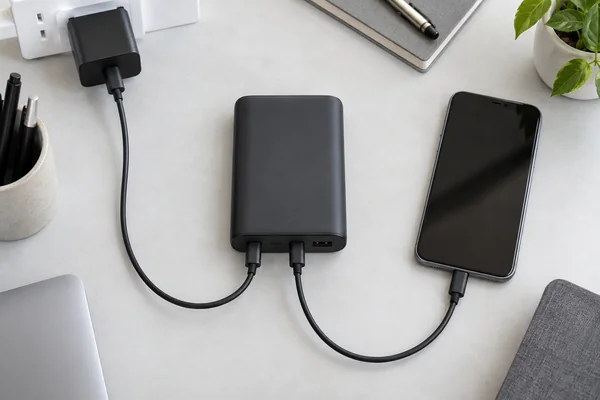
Draw the connections for each variant before testing. Include receptacles, built-in cables, wireless output, and an integrated AC plug where applicable. Mark the combinations that can operate at once. Hardware or firmware may differ within a product family, so the approved matrix must identify the purchased SKU.
| Operating mode | What the buyer should confirm | Evidence to keep |
|---|---|---|
| Input only | Which port or cable accepts power and at which negotiated profile | Charger and cable identity, input log, battery-charge behavior |
| Output only | Which interfaces deliver power and for how long | Load curve, output contract, battery state and temperature |
| Input plus one wired output | Allowed port pair, output limit, battery priority and stability | Connection diagram, simultaneous input/output log, battery-current trend |
| Input plus wireless output | Supported alignment and device conditions; output and temperature behavior | Device and case details, wireless result, thermal record |
| Input plus multiple outputs | Supported combinations and total allocation | Per-port and total-power records, protocol events |
| Adapter connected or removed under load | Whether the device resets, disconnects or changes profile | Time-stamped power and protocol trace |
Not every model supports every row. Record unsupported combinations explicitly in the specification and user instructions. The USB-C PD specification checklist can help document each port’s separate source and sink profiles.
Measure power flow, including the battery
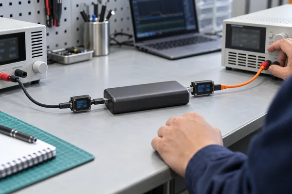
Use the adapter and cable named in the purchase specification to test the approved sample. Record input voltage and current at the power bank, output voltage and current at the load, and battery behavior on the same timeline. Save the negotiated source and sink contracts for USB-C PD modes. Repeat at defined low, intermediate, and near-full battery states; the display percentage alone is too approximate for this purpose.
Keep the time trace, not only a photo of two meters. Output may hold its rated power briefly and then fall as the cell warms or the input limit changes. A battery might charge at first, stop when a laptop draws more power, and resume when the load tapers. The trace should make those transitions visible and show whether they match the agreed operating rule.
Analog Devices describes a power-bank prototype that can charge a battery while supplying USB loads and draw on the battery when external input disappears. It is a useful design example, but a finished production sample still needs its own measurements.
Separate port ratings from simultaneous ratings
The maximum wattage printed beside each port is not a promise that both ports can reach those numbers together. For the intended combination, record the input contract, output contract, total-power limit, and sharing rule. Connect a second device as well: does the first change profile or briefly lose power?
An AC-plug power bank may have a different output limit while connected to mains than while running on its battery. Specify those modes separately. The fast-charging test guide covers single-port and shared-output measurements that complement the pass-through test.
Watch the handover when power changes
Pass-through charging is not automatically backup power. With the intended device connected and simultaneous mode running, record what happens when the external adapter is attached and removed. Repeat after a brief supply loss. Look for output gaps, resets, a new PD contract, or an automatic shutdown.
Test with representative devices as well as a controlled load. A phone may tolerate a brief renegotiation that restarts another device. Name the devices and cables in the report. Marketing should say “no interruption” only when the agreed setup and measured result support it.
Starting battery state also matters. A nearly empty pack may react differently when the adapter is unplugged. If continuous output is a requirement, define the permitted interruption and verify it under the specified starting conditions. The supplier should say plainly whether the feature is for convenience charging or an actual backup-power application.
Check sustained operation and temperature
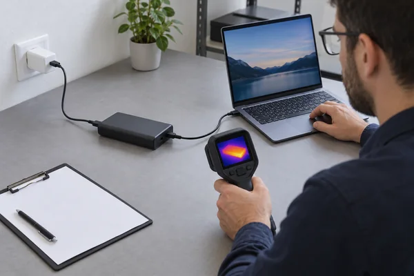
With input and output active, several power stages may be working at once. The lab or qualified engineering team should log input, output, battery current, and temperature for the duration required by the intended use. Record where temperature is measured and specify the ambient conditions, enclosure, cable, adapter, and starting battery state. Note power reduction, repeated restarts, and charging pauses.
Do not borrow a temperature limit from another power bank. Limits and stop conditions depend on the approved cell, components, housing, applicable requirements, and test method; an engineer should set them before testing. A warm enclosure tells you little about the temperature of the connector, controller, or battery. The power-bank safety testing guide addresses protection and abnormal-condition checks separately.
Build a pass-through acceptance record
Keep a completed record with the approved sample and product specification. The following fields can also form the supplier test brief.
| Field | Entry to agree before testing |
|---|---|
| Product identity | Buyer SKU, factory model, capacity variant, cell, PCBA and firmware revision |
| Input path | Port or AC plug, adapter, cable, supported profile and input limit |
| Output path | Port, built-in cable or wireless mode, target device or load, supported profile |
| Supported combinations | Permitted and prohibited simultaneous modes, including multiple outputs |
| Battery rule | Expected charging, holding or supplementing behavior at each defined load |
| Power allocation | Output limit, total limit, priority and any permitted reduction |
| Transition rule | Expected behavior when input is connected, removed or interrupted |
| Test conditions | Starting battery state, ambient condition, operating duration and measurement points |
| Acceptance decision | Numerical or observable limits, failed-mode action and approver |
A pass stamp is not enough. Keep the raw time series, sample identity, instrument details, connection diagram, abnormal events, and approval decision. If a mode fails, record the corrective action and retest the revised hardware or firmware. The passing report should identify the production revision it covers.
The power-bank product specification guide covers the wider order document, including battery, packaging, compliance, and other operating modes. Reference the exact pass-through test report in the signed sample approval.
Match the claim to the approved product
Compare the tested mode with the wording on the label, box, manual, and online listing. “Pass-through charging” is too broad if it works only with a particular adapter or port pair, or at a lower output than normal battery operation. State the permitted connection, rated output in that mode, and any charging or handover limitation users need to know. The label and manual checklist helps keep those descriptions aligned.
The approved configuration should identify the cell, PCBA, controller settings, firmware, ports, and cables. A change to any of them may affect power allocation, source/sink behavior, or heat. Link the change review to affected lots and repeat the relevant tests. The BOM and change-control guide explains how to connect that approval to production records.
Frequently asked questions
1. Can every power bank charge itself and a phone at the same time?
No. Simultaneous operation needs a supported port combination and a suitable power path. Check the exact SKU and firmware; USB-C ports alone do not establish the feature.
2. Does pass-through mean the power bank’s battery is charging?
No. While the connected device receives power, the internal battery may charge slowly, hold its level, or help supply the load. Measure its behavior during the simultaneous mode.
3. Is the output wattage the same as when the power bank runs on battery?
Not necessarily. It depends on input power, port allocation, load, battery state, and thermal controls. Obtain a separate pass-through rating and test result.
4. Will a laptop stay on if the wall adapter is unplugged?
That depends on both the power bank and the laptop. Test the transition with the intended laptop and cable, and record any output gap or PD renegotiation. A pass-through claim is not a UPS guarantee.
5. Can a USB-C port marked “input/output” do both at once?
The marking describes the directions the port can support. It says nothing about which ports can operate simultaneously. Check the approved port-pair matrix.
6. What should an OEM buyer request before approving the feature?
Request the port-combination matrix, PD contract records where applicable, synchronized input/output and battery measurements, temperature and handover logs, and final label and manual wording. Each record should identify the approved sample and production revision.
For a model-specific review, send YULIDA the intended devices, adapter and cable, required port combination, target market, and planned order quantity through the contact page. Request a written pass-through specification and sample test plan before approving the claim.
Official sources and verification
These primary sources support standards, compatibility, safety, or transport statements discussed in this article. Confirm the current requirement for the exact product model and destination market.
- USB Implementers Forum — USB Type-C and USB Power Delivery specifications and guidance.
